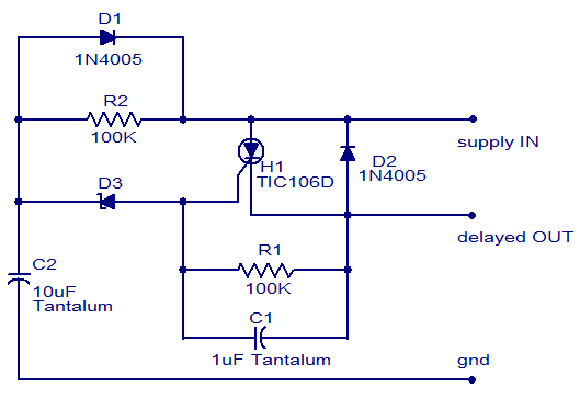
When the other transistor is open, it should act as a NOT switch, taking the charge from the second cap and sending it to neutral instead of through the 10kOhm resistor, but instead when I tested the circuit on a perf board with a 3V coin battery cell as a power supply, it provides no output, regardless of whether or not the button is pushed. It works with two switches, one for rest and the. You can also control motors, create an alarm, create a musical instrument, and much more. But that’s just one simple example of the many things you can do with this chip. One of the first things many do with it is to create a blinking light.
#SIMPLE DELAY TIMER CIRCUIT HOW TO#
On activation of the momentary push button switch, the capacitor should fill up then slowly discharge through the 100kOhm resistor into both transistors' bases, opening the flow into the other capacitor (connected to transistor 2) which then continually discharges and refills until the first capacitor runs out of charge and the transistor is closed, when the second cap finally discharges through the only open path (through the 10kOhm resistor into the load). The 555 delay IC circuit is a popular, versatile, and simple timer manufacturers use to design other circuits. In this 555 Timer tutorial, you’ll learn how to use the 555 timer to do fun things. In order for the output to go high, the reset pin of 555 timer (pin 4) must be high and the. In this Delay Timer project, all analog parts are being used with the thyristor as a device that switches an AC Relay ON or OFF depending on the timing of. The timing of the delay can also be changed by changing the resistor value of VR1 and the capacitor value of E based on the time delay formula of t0.69RC. The time delay circuit also comes with a potentiometer to adjust the time delay by rotating it. It works with two switches, one for rest and the other to begin the delay time. The figures below show different schematics of simple timer circuits, which can. This circuit uses a 555 timer to delay a pulse that comes in to a maximum time of 75 seconds. The 555 delay IC circuit is a popular, versatile, and simple timer manufacturers use to design other circuits. A shift register is a cascade of flip flops, sharing the same clock, in which the output of each flip-flop is. A simple timer circuit can be built by using only a single or two transistors. And to calculate the component values for a given delay time, it is easier to fix the value of capacitor and calculate the resistor value.

2 Starter 1M energizes immediately, but the timer does not start timing. For example, in the circuit diagram of the fixed delay duration timer, we have used a 68K resistor and 470uF capacitor which gives us a delay time of: T 1.1 (68000) (0.000470) 32 seconds. I made a circuit schematic for a simple discrete capacitor+resistor time delay circuit, using a 1500uf capacitor and a 100kOhm resistor as a timing mechanism. Simple Delay Circuit can be constituted by. 1 Basic circuit to change the logic of an on-delay timer into an off-delay timer. Simulate this circuit – Schematic created using CircuitLab


 0 kommentar(er)
